Flexible PCB – Everything You Need To Know About It
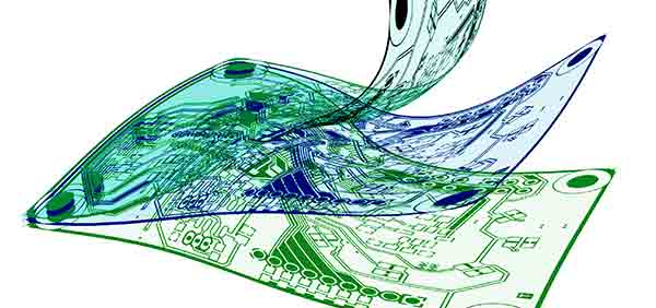
Flexible PCBs are an evolving trend in printed electronics. The boards possess the unique feature of being able to conform to any designated shape because of the laminate used in the composition. The laminate characteristics do not just have an impact on the manufacturing processes – it also positively affects the performance of the manufactured circuit board. Dielectric substrates and the conducting foils make up the laminate of the flexible PCBs. Read on to know more about this amazing technology.

Why did the need for flexible PCBs arise?
Earlier, only rigid PCBs were manufactured. However, as the technology progressed, the need for miniaturization became more intense – the printed circuit boards simply had to be made lightweight, diminutive and as slim as possible without compromising on the wiring density. The flexible PCBs came to aid. With their ability to get wired in 3 dimensions and change the shape to fit in limited space, the flexible PCB technology has opened doors to the ongoing research domains of the flexible electronics.
Substrate materials
The base or the dielectric substrate materials can primarily be classified into two major categories:
- Thermosetting Plastics
- Thermoplastics
Thermosetting plastics are synthetically made materials which do not have the ability to soften upon heating unlike thermoplastics. Examples of thermosetting plastics include polyacrylate and polyimide. Thermoplastic flex circuits are made up of amorphous polymers, fluorinated hydrocarbons and polyester which gives the flex circuits the elastic properties.
Types of Flexible PCBs
Majorly, flexible PCBs can be classified into the following types:
- Single Sided Flex PCBs: Conductive metal traces are only on a single side of the flexible PCBs.
- Double Sided Flex PCBs: Conductive metal traces are on both sides of the dielectric substrate. Layers are normally connected by metallic thru-holes.
- Multi-layered Flex PCBs: There are several layers of conductive copper that are isolated from each other because of the dielectric medium in between.
Nowadays, rigid flex PCBs are also available in which some of the layers are made up of hard printed boards and some follow the mechanics of the flexible electronics.
Benefits of Flexible Circuit Technology
The flexible PCBs provide a plethora of options to the designer because of their ability get folded, bent and configure itself to varying thickness and shape. With the traditional packaging, there are a lot of limitations on the size and space; this is not the case with flex circuits. The thickness of these circuit boards can be as little as 0.004 inches! The assembly costs are less expensive as well for two reasons:
- These circuits can be tested before the components are assemble
- The technology assists in eliminating the number of solder joints and connects.
Flex PCBs are made up of high temperature resistive materials like polyimide which have the better thermal management characteristics and dissipate heat efficiently, allowing flexible circuits to be used in high power circuits.
Flexible PCB Fabrication
Like in rigid PCB fabrication, flexible PCBs can also be fabricated through two processes, namely, subtractive and additive processes. In the former process, the solid metallic space is made clear of unwanted metal to create traces. The circuit pattern is defined through either screen printing or photo imaging. This process is economic, robust and has more choices that can be incorporated in the final products. The latter process begins with the dielectric layer upon which the conductive metallic traces are laid to form the circuit.
There are numerous methods of adding the printed circuit layers to the PCBs. Connector insertion, surface mounted assembly and wire bonding follow later on. The assembly options for flex circuits are infinite. Only your imagination limits you from unlocking the inherent potential of the flexible electronics!
